

Mfr Part # 20168
THING PLUS ESP32 WROOM USB-C
SparkFun Electronics

Courtesy of SparkFun
Guide by SANTAIMPERSONATOR, BRUDNERD
Introduction
Note: This guide is specific to the ESP32 Thing Plus (USB-C) board variant. For the variants with the USB micro-B connector, please refer to the ESP32 Thing Plus hookup guide.
The SparkFun ESP32-WROOM Thing Plus (USB-C) enjoys all the features of our previous ESP32 Thing Plus (Micro-B) boards, but with a few improvements. For this variant, we have included a SD card slot, upgraded to a USB-C connector, integrated a RGB status LED and battery fuel gauge, and provided two voltage regulators: offering separate 700mA current sources for the board and Qwiic connector. The board still retains its standardized 28-pin Feather footprint, 2-pin JST battery connector, and Qwiic connector like our other Thing Plus boards.
SparkFun Thing Plus - ESP32 WROOM (USB-C)
The ESP32-WROOM module on the board provides a rich set of peripherals, ranging from capacitive touch sensors, SD card interface, Ethernet, high-speed SPI, UART, I2S, and I2C. With Espressif's ESP32 comprehensive development platform and Bluetooth low-energy support (i.e. BLE, BT4.0, Bluetooth Smart) these boards are jam packed with possibilities!
Note: The CH340C serial-to-UART bridge is used on this board. Therefore, a different driver installation is required from previous versions of the ESP32 Thing Plus.
Not Yet Implemented: The Arduino core for the ESP32 microcontroller is still a work in progress. There are a handful of peripherals and features that have yet to be implemented, including:
The peripherals are available (if, also, still in their infancy) in the IoT Development Framework for the ESP32. If your application requires any of the features above, consider giving the ESP-IDF a try! (Updated: June 2022.)
Required Materials
To get started, users will need a few items. Now some users may have a few of these items, feel free to modify your cart accordingly.
HEADERS
Headers & Accessories
Headers are great for development purposes, letting users swap parts with just a set of jumper wires. If you would like to add headers to your board, check out some of the options for the Thing Plus or Feather form factor boards below. For a full selection of our available Headers or Soldering Tools, click on the associated links.
New to soldering? Check out our Through-Hole Soldering Tutorial for a quick introduction!
How to Solder: Through-Hole Soldering
This tutorial covers everything you need to know about through-hole soldering.
BATTERIES
Li-Po Battery
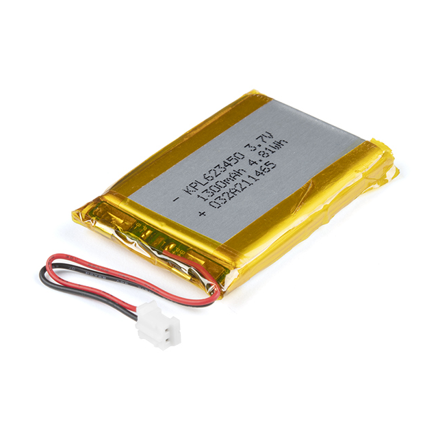
For mobile applications, users will want to pick up a single-cell LiPo battery from our catalog. Below, are a few available options:
JUMPER MODIFICATION
Jumper Modification
To modify the jumpers, users will need soldering equipment and/or a knife.
New to jumper pads? Check out our Jumper Pads and PCB Traces Tutorial for a quick introduction!
How to Work with Jumper Pads and PCB Traces
Handling PCB jumper pads and traces is an essential skill. Learn how to cut a PCB trace, add a solder jumper between pads to reroute connections, and repair a trace with the green wire method if a trace is damaged.
Suggested Reading
As a more professionally oriented product, we will skip over the more fundamental tutorials (i.e. Ohm's Law and What is Electricity?). However, below are a few tutorials that may help users familiarize themselves with various aspects of the board.
One of the new, advanced features of the board is that it takes advantage of the Qwiic connect system. We recommend familiarizing yourself with the Logic Levels and I2C tutorials. Click on the banner above to learn more about Qwiic products.
Hardware Overview
Note: All mentions of GPIO in this section will refer to the I/O pins of the ESP32-WROOM module as represented in the datasheets and pin numbers of the board definition in the ESP32 Arduino core. They do not correspond with the net names for the Thing Plus Form Factor device in the schematic. (The device in the schematic is primarily, used internally to facilitate the board design process; just ignore the naming of the GPIO0 - GPIO6 nets.)
Board Dimensions
The board dimensions are illustrated in the drawing below. The listed measurements are in inches and the two mounting holes are compatible with 4-40 standoff screws.
Board dimensions (PDF) for the ESP32-WROOM Thing Plus, in inches.
USB-C Connector
The USB connector is provided to power and program the board. For most users, it will be the primary programing interface for the ESP32.
USB-C connector on the ESP32-WROOM Thing Plus.
CH340 Serial-to-UART
The CH340 allows the ESP32-WROOM to communicate with a computer/host device through the board's USB-C connection. This allows the board to show up as a device on the serial (or COM) port of the computer. Users will need to install the latest drivers for the computer to recognize the board (see Software Overview section).
Power
The ESP32-WROOM Thing Plus only requires 3.3V to power the board. However, the simplest method to power the board is through the USB-C connector. Alternatively, the 3V3, VBAT, and VUSB pins can also be used to supply power to the board.
ESP32-WROOM Thing Plus power connections.
Below, is a general summary of the power circuitry on the board:
For more details, users can reference the schematic and the datasheets of the individual components in the power circuitry.
Power Status LED
The red, PWR LED will light up once 3.3V is supplied to the board; however, for most users, it will light up when 5V is supplied through the USB connection or when a LiPo battery is connected to the JST connector.
ESP32-WROOM Thing Plus PWR status LED indicator.
Charging Circuit
The charging circuit utilizes the MCP73831 linear charge management controller and is powered directly from the USB-C connector or VUSB. The controller is configured for a 500mA charge rate and active charging is indicated by the yellow, CHG LED. If the charge controller is shutdown or charging is complete, the CHG LED will turn off. For more information, please refer to the MCP73831 datasheet and the Indicator LEDs section below.
Power Control
The power source for the XC6222 LDO voltage regulators is controlled by a P-channel MOSFET. In addition, the 3.3V regulated output from the XC6222 LDOs are enabled by the control pin (CE).
Circuits for the 3.3V power on the ESP32-WROOM Thing Plus.
The P-channel MOSFET operates based on the voltages at the MOSFET's gate and source pins. Depending on the power supplies connected to the board, the MOSFET will switch between the battery and USB-C connection as power sources for the XC6222 voltage regulators.
The control pin (CE) of the XC6222 LDOs also provides an additional amount of control for the board's power. By default, the regulated 3.3V output is enabled. To disable and shutdown the output voltage from the XC6222, the control pin needs to be pulled low (i.e., shorted to ground (GND)). For more information, please refer to the XC6222 datasheet.
XC6222 control pins on the ESP32-WROOM Thing Plus.
Note: The BOOT button is also connected to GPIO 0. Therefore, pressing the BOOT button will momentarily disable power to the Qwiic connector.
Current Consumption
According to the specifications, the ESP32-WROOM draws about 240 mA during RF transmissions. With the Wi-Fi example in this tutorial, have measured it to average around 140 mA and peak at 300 mA while actively transceiving. The table below, summarizes the approximate current draw of the ESP32-WROOM Thing Plus (USB-C) for various operational conditions. The measurements in the table below, were made with the Nordic Power Profiler Kit II.
It is possible for users to reach sub-mA power consumption levels with the deep sleep power modes. Using the TimerWakeUp Deep Sleep example code, the LED jumpers cut, and powering the board through the LiPo battery connection we measured a power consumption of 845 µA (990 µA peak) @ 3.7V while the MCU was inactive.
The current measurement from VBAT at 3.7V during deep sleep.
ESP32-WROOM
This variant of the ESP32 Thing Plus is designed around the ESP32-WROOM module with 16MB of flash memory. Espressif's ESP32-WROOM module is a versatile, WiFi BT BLE MCU module that targets a wide variety of applications. At the core of this module is the ESP32-D0WDQ6 system on a chip (SoC) which is designed to be both scalable and adaptive. Its laundry list of features include:
Note: Users should be aware of the following nuances and details of this board
ESP32-WROOM module on the ESP32 Thing Plus (USB-C).
Note: The ESP32-WROOM module has various power modes:
For more information on the power management of the ESP32-WROOM module, please refer to Section 3.7 and Tables: 8 and 17 of the ESP32 SoC Datasheet.
Debugging
For users interested in debugging their code, the JTAG pins are broken out on the board. However, the debugging feature is only available through the ESP-IDF.
Note: Users should be aware that GPIO 13 is connected to the STAT LED with a pull-down resistor.
Firmware Download Mode
Users can manually force the board into the serial bootloader with the BOOT button. Please, refer to the Boot Button section below for more information.
Peripherals and I/O
Note: Users should be aware of the following nuances of this board.
The ESP32-WROOM module has 26 multifunctional GPIO, of which, 21 I/O pins broken out into a feather form factor layout on this board. All of the ESP32-WROOM Thing Plus (USB-C) pins have a .1" pitch spacing for headers. With the pin multiplexing capabilities of the ESP32 SoC, various pins can have several functionalities. For more technical specifications on the I/O pins, please refer to the ESP32 SoC datasheet.
Graphical datasheet for the ESP32-WROOM Thing Plus (USB-C).
Note: Users should be aware of the following limitations for the board in the Arduino IDE.
For digital pins, users will need to declare the pinMode() (link) in the setup of their sketch (programs written in the Arduino IDE) for the pins used.
Input
When configured properly, an input pin will be looking for a HIGH or LOW state. Input pins are High Impedance and takes very little current to move the input pin from one state to another.
Output
When configured as an output the pin will be at a HIGH or LOW voltage. Output pins are Low Impedance: This means that they can provide a relatively substantial amount of current to other circuits.
Note: There are electrical limitations to the amount of current that the ESP32-WROOM module can sink or source. For more details, check out the ESP32-WROOM module datasheet.
Additional Functions
There are several pins that have special functionality in addition to general digital I/O. These pins and their additional functions are listed in the tabs below. For more technical specifications on the I/O pins, you can refer to the schematic, ESP32-WROOM module datasheet, ESP32 SoC datasheet, and documentation for the ESP32 Arduino core.
ANALOG INPUT
Analog Input Pins
The ESP32-WROOM module provides a 12-bit ADC input on thirteen of its I/O pins. This functionality is accessed in the Arduino IDE using the analogRead(pin) function. (*The available ADC pins are highlighted in the image below.)
Analog input pins on the ESP32-WROOM Thing Plus.
Note: By default, in the Arduino IDE, analogRead() returns a 10-bit value. To change the resolution of the value returned by the analogRead() function, use the analogReadResolution(bits) function.
Note: To learn more about analog vs. digital signals, check out this great tutorial.
This tutorial covers the concept of analog and digital signals, as they relate to electronics.
PWM/ANALOG OUTPUT
Pulse Width Modulation (PWM) and Analog (DAC) Output Pins
The ESP32-WROOM module supports up to sixteen channels of 20-bit PWM outputs on any of its I/O pins. This is accessed in the Arduino IDE using the analogWrite(pin, value) function or the LED Control API. (*Any I/O pin can be used for the PWM outputs; the available DAC pins, with true analog outputs, are highlighted in the image below.)
Any I/O pin can be used for a PWM output, but these are the DAC pins on the ESP32-WROOM Thing Plus.
Note: By default, in the Arduino IDE, analogWrite() accepts an 8-bit value. To change the resolution of the PWM signal for the analogWrite() function, use the analogWriteResolution(bits) function.
(*The PWM output is not a true analog signal. For a true analog output, please refer to the DAC API for GPIO 25 and GPIO 26.)
Note: To learn more about pulse width modulation (PWM), check out this great tutorial.
An introduction to the concept of Pulse Width Modulation.
SERIAL COMM.
Serial Communication Pins
The ESP32-WROOM module provides three UART ports. By default, the UART port for the USB connection (Serial) and the labeled UART I/O pins on the board (Serial1) can be accessed through the Arduino IDE using the serial communication class.
Default UART ports on the ESP32-WROOM Thing Plus.
Note: By default, in the Arduino IDE, the SparkFun ESP32 Thing Plus C board definition supports:
In order to utilize the serial communication on the strapping pins, users will need to create a custom serial port object and declare which pins to access.
Note: To learn more about serial communication, check out this great tutorial.
Asynchronous serial communication concepts: packets, signal levels, baud rates, UARTs and more!
Note: We have noticed that with the ESP32 Arduino core, Serial.available() does not operate instantaneously. This is due to an interrupt triggered by the UART, to empty the FIFO when the RX pin is inactive for two-byte periods:
For more information, please refer to this chatroom discussion.
SPI
SPI Communication
The ESP32-WROOM module provides three SPI buses. By default, in the Arduino IDE, the SPI class is configured to utilize pins GPIO 18 (SCK), GPIO 19 (POCI), GPIO 23 (PICO). These pins share the same SPI bus as the µSD card slot, which utilizes pin 5 (SS) for its chip select. In order to utilize the other SPI ports or objects, users will need to create a custom SPI object and declare which pins to access.
Note: To comply with the latest OSHW design practices, we have adopted the new SPI signal nomenclature (SDO/SDI and PICO/POCI). The terms Master and Slave are now referred to as Controller and Peripheral. The MOSI signal on a controller has been replaced with SDO or PICO. Please refer to this announcement on the decision to deprecate the MOSI/MISO terminology and transition to the SDO/SDI naming convention.
Default SPI bus connections on the ESP32-WROOM Thing Plus.
Note: To learn more about the serial peripheral interface (SPI) protocol, check out this great tutorial.
Serial Peripheral Interface (SPI)
SPI is commonly used to connect microcontrollers to peripherals such as sensors, shift registers, and SD cards.
I2C
I2C Communication Pins
The ESP32-WROOM module can support up to two I2C buses. By default, in the Arduino IDE, the Wire class is configured to utilize pins GPIO 21 (SDA) and GPIO 22 (SCL). These pins share the same I2C bus with the Qwiic connector and MAX17048 fuel gauge. In order to utilize the other I2C ports, users will need to create a custom Wire object and declare which pins to access.
Default I2C bus connections for the ESP32-WROOM Thing Plus.
Note: To learn more about the inter-integrated circuit (I2C) protocol, check out this great tutorial.
An introduction to I2C, one of the main embedded communications protocols in use today.
Buttons
There are two buttons on ESP32-WROOM Thing Plus: an RST and BOOT button.
Reset Button
The RST (reset) button allows users to reset the program running on the ESP32-WROOM module without unplugging the board.
RST button on the ESP32-WROOM Thing Plus.
Boot Button
The BOOT button can be used to force the board into the serial bootloader. Holding down the BOOT button, while connecting the board to a computer through its USB-C connector or resetting the board will cause it to enter the Firmware Download mode. The board will remain in this mode until it power cycles (happens automatically after uploading new firmware) or the RST button is pressed.
1. Hold the BOOT button down
2. Reset the MCU
o While unpowered, connect the board to a computer with through the USB-C connection
o While powered, press the RST button
3. Release the BOOT button
4. After programming is completed, reboot the MCU
BOOT button on the ESP32-WROOM Thing Plus.
Note: The BOOT button is also connected to GPIO 0, which controls the voltage output to the Qwiic connector. Therefore, pressing the BOOT button will momentarily disable power to the Qwiic connector.
Indicator LEDs
There are four indicator LEDs on the ESP32-WROOM Thing Plus:
Power LED
The red, power (PWR) LED will light up once 3.3V is supplied to the board. For most users, it will light up when 5V is supplied through the USB connection and/or when a LiPo battery is attached to the JST connector.
ESP32-WROOM Thing Plus PWR status LED indicator.
Battery Charging LED
The yellow, battery charging (CHG) LED indicates the status of the MCP73831 charge management controller. The LED will shut off when no battery is present, when the charge management controller is in standby (after the battery charging has been completed), or when the charge management controller is shutdown. The LED will illuminate when the charge management controller is in the process of charging the battery. For more information, please refer to the MCP73831 datasheet.
The battery charging (CHG) LED indicator on the ESP32-WROOM Thing Plus.
STAT LED
The blue, status (STAT) LED is typically used as a test or status LED to make sure that a board is working or for basic debugging. This indicator is connected to GPIO 13.
The status (STAT) LED indicator on the ESP32-WROOM Thing Plus.
WS2812 RGB LED
The WS2812 RGB LED is controlled with a 24-bit (GRB) data signal. This indicator is connected to GPIO 02 and the digital output pin from the LED is available through a test point. For more information, please refer to the WS2812C datasheet.
WS2812 LED indicator on the ESP32-WROOM Thing Plus.
Note: The latest ESP32 Arduino core, now provides a basic RGB LED driver for a WS2812 (or NeoPixel) LED populated the board. For an example of how to utilize the RGB LED driver check out the BlinkRGB example code, which can be accessed from the File drop down menu (i.e File > Examples > ESP32 > GPIO > BlinkRGB).
µSD Slot
Note: To comply with the latest OSHW design practices, we have adopted the new SPI signal nomenclature (SDO/SDI and PICO/POCI). The terms Master and Slave are now referred to as Controller and Peripheral. Please refer to this announcement on the decision to transition to the new naming convention.
The ESP32-WROOM Thing Plus (USB-C) includes an µSD card slot. This is great for data logging applications or storing files. The µSD card slot is connected to the following dedicated GPIO:
µSD card slot on the ESP32-WROOM Thing Plus.
Jumpers
There are two jumpers on the back of the board that can be used to easily modify the hardware connections on the board.
Traces around the CHG LED jumper.
The jumpers on the back of the ESP32-WROOM Thing Plus.
Never modified a jumper before? Check out our Jumper Pads and PCB Traces tutorial for a quick introduction!
How to Work with Jumper Pads and PCB Traces
Handling PCB jumper pads and traces is an essential skill. Learn how to cut a PCB trace, add a solder jumper between pads to reroute connections, and repair a trace with the green wire method if a trace is damaged.
Primary I2C Bus
The Qwiic connector and battery fuel gauge are attached to the primary I2C bus. The primary I2C bus for this board utilizes the pin connections, detailed in the table below:
Battery Fuel Gauge
The MAX17048 fuel gauge measures the approximate charge or discharge rate, state of charge (SOC) (based on ModelGauge algorithm), and voltage of a connected battery. Additionally, the chip is powered directly from VBAT, when a LiPo battery is connected. For more information, please refer to the MAX17048 datasheet.
The MAX17048 fuel gauge on the ESP32-WROOM Thing Plus.
Note: The Alert pin for the MAX17048 is not connected and cannot be utilized.
Qwiic Connector
A Qwiic connector is provided for users to seamlessly integrate with SparkFun's Qwiic Ecosystem.
Qwiic connector and I2C pins on the ESP32-WROOM Thing Plus.
Power Control
In order to enable power for the Qwiic connector, users must toggle GPIO 0 high. This enables the power output from the XC6222 LDO regulator to the Qwiic connector, which can source up to 700mA at 3.3V . In order to conserve battery power or in low power applications, users can toggle GPIO 0 low, to disable the power to the Qwiic connector.
Note: GPIO 0 is also connected to the BOOT button. Therefore, pressing the BOOT button will momentarily disable power to the Qwiic connector.
What is Qwiic?
The Qwiic system is intended a quick, hassle-free cabling/connector system for I2C devices. Qwiic is actually a play on words between "quick" and I2C or "iic".
Features of the Qwiic System
NO SOLDERING
Keep your soldering iron at bay.
Cables plug easily between boards making quick work of setting up a new prototype. We currently offer three different lengths of Qwiic cables as well as a breadboard friendly cable to connect any Qwiic enabled board to anything else. Initially you may need to solder headers onto the shield to connect your platform to the Qwiic system but once that’s done it’s plug and go!
Qwiic cables connected to Spectral Sensor Breakout
POLARIZED CONNECTOR
Minimize your mistakes.
How many times have you swapped the SDA and SCL wires on your breadboard hoping the sensor will start working? The Qwiic connector is polarized so you know you’ll have it wired correctly, every time, from the start.
The PCB connector is part number SM04B-SRSS (Datasheet) or equivalent. The mating connector used on cables is part number SHR04V-S-B or equivalent. This is a common and low-cost connector.
1mm pitch, 4-pin JST connector
DAISY CHAIN
Expand with ease.
It’s time to leverage the power of the I2C bus! Most Qwiic boards will have two or more connectors on them allowing multiple devices to be connected.
Shown above: Qwiic Shield for Arduino on RedBoard, Spectral Sensor Breakout - NIR, Spectral Sensor Breakout - Visible, and SparkFun GPS Breakout
Hardware Assembly
USB Programming
The USB connection is utilized for programming and serial communication. Users only need to plug their ESP32-WROOM Thing Plus into a computer using a USB-C cable.
The ESP32-WROOM Thing Plus with USB-C cable attached.
Battery
For remote IoT applications, a Li-Po battery can be connected. Additionally, users may be interested in utilizing a solar panel and USB-C cable to recharge their battery.
The ESP32-WROOM Thing Plus with a battery connected.
Note: DO NOT remove batteries by pulling on their wires. Instead, it is recommended that pair of dikes (i.e., diagonal wire cutters), pliers, or tweezers be used to pull on the JST connector housing, to avoid damaging the battery wiring.
Using a pair of dikes to disconnect a battery.
Headers
The pins for the ESP32-WROOM Thing Plus are broken out to 0.1"-spaced pins on the outer edges of the board. When selecting headers, be sure you are aware of the functionality you need. If you have never soldered before or need a quick refresher, check out our How to Solder: Through-Hole Soldering guide.
Soldering headers to the ESP32-WROOM Thing Plus.
The Feather Stackable Header Kit is a great option as it allows users to stack shields (w/ Feather footprint) or it can be placed on the a breadboard; while, the pins are still accessible from the female/male headers.
µSD Card Slot
The ESP32-WROOM Thing Plus (USB-C) includes a µSD card slot on the back of the board. The card holder functions through a push/pull operation. (The card slot doesn't include a spring retention mechanism; cards are held in place through friction.)
Users can slide-in or pull-out a µSD card from the card holder.
Qwiic Devices
The Qwiic system allows users to effortlessly prototype with a Qwiic compatible I2C device without soldering. Users can attach any Qwiic compatible sensor or board, with just a Qwiic cable. (*The example below, is for demonstration purposes and is not pertinent to the board functionality or this tutorial.)
The BME688 environmental and VL53L1X distance Qwiic sensor boards connected to the ESP32-WROOM Thing Plus.
Software Overview
CH340 Driver
Users will need to install the appropriate driver for their computer to recognize the serial-to-UART chip on their board/adapter. Most of the latest operating systems will recognize CH340C chip on the board and automatically install the required driver.
To manually install the CH340 driver on their computer, users can download it from the WCH website. For more information, check out our How to Install CH340 Drivers Tutorial.
How to install CH340 drivers (if you need them) on Windows, Mac OS X, and Linux.
Arduino IDE
Note: For first-time users, who have never programmed before and are looking to use the Arduino IDE, we recommend beginning with the SparkFun Inventor's Kit (SIK), which includes a simpler board like the Arduino Uno or SparkFun RedBoard and is designed to help users get started programming with the Arduino IDE.
Most users may already be familiar with the Arduino IDE and its use. However, for those of you who have never heard the name Arduino before, feel free to check out the Arduino website. To get started with using the Arduino IDE, check out our tutorials below:
Install Board Definition
Install the latest ESP32 board definitions in the Arduino IDE.
Installing Board Definitions in the Arduino IDE
How do I install a custom Arduino board/core? It's easy! This tutorial will go over how to install an Arduino board definition using the Arduino Board Manager. We will also go over manually installing third-party cores, such as the board definitions required for many of the SparkFun development boards.
Note: For more instructions, users can follow this tutorial on Installing Additional Cores provided by Arduino. Users will also need the .json file for the Espressif Arduino core:
https://raw.githubusercontent.com/espressif/arduino-esp32/gh-pages/package_esp32_index.json
When selecting a board to program in the Arduino IDE, users should select the SparkFun ESP32 Thing Plus C from the Tools drop down menu (i.e., Tools > Board > ESP32 Arduino > SparkFun ESP32 Thing Plus C). Alternatively, users can also select the ESP32 Dev Module; however, they may lose some pin assignments (i.e., LED_BUILTIN).
Selecting the SparkFun ESP32 Thing Plus C from the Tools drop down menu in the Arduino IDE.
Note: In the Arduino 2.0.x IDE users can also select the board from the Select Board drop down menu and search for the SparkFun ESP32 Thing Plus C:
Selecting the SparkFun ESP32 Thing Plus C in the Arduino 2.0.x IDE.
Arduino Example: Blink
First-Time Users:
With the driver and ESP32 Arduino core installed, users are ready to program their board! When selecting a board to program, users should select the SparkFun ESP32 Thing Plus C in the Arduino IDE.
Once the ESP32 Thing Plus is connected to a computer with a USB cable, the board will be assigned a unique port identifier. On Windows machines, this should appear as COM#, and on Macs or Linux computers it should be /dev/tty.usbserial-####### in the Arduino IDE. Before code can be uploaded, users will need to select the port that the board has been assigned to.
Loading Blink
To make sure the toolchain and board are properly set up, let us try to upload a simple sketch! The STAT LED attached to GPIO 13 is perfect for a simple test. Copy and paste the example sketch below into a fresh Arduino sketch:
int ledPin = 13;

void setup()
{
    pinMode(ledPin, OUTPUT);
    Serial.begin(115200);
}

void loop()
{
    Serial.println("Hello, world!");
    digitalWrite(ledPin, HIGH);
    delay(500);
    digitalWrite(ledPin, LOW);
    delay(500);
}
With everything setup correctly, upload the code! Once the upload is complete, open the serial monitor and set the baud rate to 115200. Users should see a Hello, world! print statement begin to fly by.
If the blue LED remains dimly lit, it's probably still sitting in the bootloader. After uploading a sketch, users may need to tap the RST button to get their ESP32 Thing Plus to begin running the sketch.
Users may also notice that when the ESP32 boots up it prints out a long sequence of debug messages. These are emitted every time the chip resets -- always at 115200 baud.
Arduino Example: Wi-Fi
Note: Users should be utilizing the 2.4GHz band of their wireless router. The current ESP32 modules aren't compatible with 5GHz Wi-Fi signals; users will need to wait for the ESP32-C5 for that feature. To get notifications on our latest products, sign-up for our newsletter!
The ESP32 Arduino core includes a handful of Wi-Fi examples, which demonstrate everything from scanning for nearby networks. These Wi-Fi examples are available under the File > Examples > Wi-Fi drop-down menu in the Arduino IDE.
Below, is a more advanced example utilizing the Wi-Fi Arduino library. It demonstrates how to connect to a nearby Wi-Fi network and poll a remote domain (http://example.com/) as a client.
#include <WiFi.h>

// WiFi network name and password:
const char * networkName = "YOUR_NETWORK_HERE";
const char * networkPswd = "YOUR_PASSWORD_HERE";

// Internet domain to request from:
const char * hostDomain = "example.com";
const int hostPort = 80;

const int BUTTON_PIN = 0;
const int LED_PIN = 13;

void setup()
{
  // Initilize hardware:
  Serial.begin(115200);
  pinMode(BUTTON_PIN, INPUT_PULLUP);
  pinMode(LED_PIN, OUTPUT);

  // Connect to the WiFi network (see function below loop)
  connectToWiFi(networkName, networkPswd);

  digitalWrite(LED_PIN, LOW); // LED off
  Serial.print("Press button 0 to connect to ");
  Serial.println(hostDomain);
}

void loop()
{
  if (digitalRead(BUTTON_PIN) == LOW)
  { // Check if button has been pressed
    while (digitalRead(BUTTON_PIN) == LOW)
      ; // Wait for button to be released

    digitalWrite(LED_PIN, HIGH); // Turn on LED
    requestURL(hostDomain, hostPort); // Connect to server
    digitalWrite(LED_PIN, LOW); // Turn off LED
  }
}

void connectToWiFi(const char * ssid, const char * pwd)
{
  int ledState = 0;

  printLine();
  Serial.println("Connecting to WiFi network: " + String(ssid));

  WiFi.begin(ssid, pwd);

  while (WiFi.status() != WL_CONNECTED)
  {
    // Blink LED while we're connecting:
    digitalWrite(LED_PIN, ledState);
    ledState = (ledState + 1) % 2; // Flip ledState
    delay(500);
    Serial.print(".");
  }

  Serial.println();
  Serial.println("WiFi connected!");
  Serial.print("IP address: ");
  Serial.println(WiFi.localIP());
}

void requestURL(const char * host, uint8_t port)
{
  printLine();
  Serial.println("Connecting to domain: " + String(host));

  // Use WiFiClient class to create TCP connections
  WiFiClient client;
  if (!client.connect(host, port))
  {
    Serial.println("connection failed");
    return;
  }
  Serial.println("Connected!");
  printLine();

  // This will send the request to the server
  client.print((String)"GET / HTTP/1.1\r\n" +
               "Host: " + String(host) + "\r\n" +
               "Connection: close\r\n\r\n");
  unsigned long timeout = millis();
  while (client.available() == 0)
  {
    if (millis() - timeout > 5000)
    {
      Serial.println(">>> Client Timeout !");
      client.stop();
      return;
    }
  }

  // Read all the lines of the reply from server and print them to Serial
  while (client.available())
  {
    String line = client.readStringUntil('\r');
    Serial.print(line);
  }

  Serial.println();
  Serial.println("closing connection");
  client.stop();
}

void printLine()
{
  Serial.println();
  for (int i=0; i<30; i++)
    Serial.print("-");
  Serial.println();
}
Make sure to fill in the networkName and networkPswd variables, at the beginning of the sketch, with the name (or SSID) and password of your Wi-Fi network! Once that is done, upload the sketch to the board and open the Serial Monitor of the Arduino IDE.
Example of the report out in the Serial Monitor.
After the ESP32 connects to the Wi-Fi network, it will wait for the user to press the BOOT button. Tapping the button will cause the ESP32 to make an HTTP request to example.com. The board should return a string of HTTP headers and HTML code, as shown above.
Arduino Example: BLE
Note: This example requires a compatible BLE app on a smart phone. We recommend the BLE Scanner for iPhone or Android. Also, don't forget to enable the Bluetooth connection on the phone.
The ESP32 Arduino core also includes several Bluetooth examples that range from acting as a simple BLE device to functioning as a Bluetooth server. This example will demonstrate how users can send messages from their phone to ESP32 Thing Plus; and then display the message in the serial monitor. Users will need to install the BLE Scanner app (iPhone or Android) on their smart phone and enable the Bluetooth connection.
The example code is built into the Arduino IDE for the ESP32 Arduino core (users need to select and ESP32 board definition first). Once an ESP32 board has been selected, the built-in BLE examples will become available; select the BLE_write example from the Files > Examples > ESP32 BLE Arduino > BLE_write drop down menu. Compile and upload the example code. Make sure the correct port has been selected for the board.
/*
    Based on Neil Kolban example for IDF: https://github.com/nkolban/esp32-snippets/blob/master/cpp_utils/tests/BLE%20Tests/SampleWrite.cpp
    Ported to Arduino ESP32 by Evandro Copercini
*/

#include <BLEDevice.h>
#include <BLEUtils.h>
#include <BLEServer.h>

// See the following for generating UUIDs:
// https://www.uuidgenerator.net/

#define SERVICE_UUID        "4fafc201-1fb5-459e-8fcc-c5c9c331914b"
#define CHARACTERISTIC_UUID "beb5483e-36e1-4688-b7f5-ea07361b26a8"


class MyCallbacks: public BLECharacteristicCallbacks {
    void onWrite(BLECharacteristic *pCharacteristic) {
      std::string value = pCharacteristic->getValue();

      if (value.length() > 0) {
        Serial.println("*********");
        Serial.print("New value: ");
        for (int i = 0; i < value.length(); i++)
          Serial.print(value[i]);

        Serial.println();
        Serial.println("*********");
      }
    }
};

void setup() {
  Serial.begin(115200);

  Serial.println("1- Download and install an BLE scanner app in your phone");
  Serial.println("2- Scan for BLE devices in the app");
  Serial.println("3- Connect to MyESP32");
  Serial.println("4- Go to CUSTOM CHARACTERISTIC in CUSTOM SERVICE and write something");
  Serial.println("5- See the magic =)");

  BLEDevice::init("MyESP32");
  BLEServer *pServer = BLEDevice::createServer();

  BLEService *pService = pServer->createService(SERVICE_UUID);

  BLECharacteristic *pCharacteristic = pService->createCharacteristic(
                                         CHARACTERISTIC_UUID,
                                         BLECharacteristic::PROPERTY_READ |
                                         BLECharacteristic::PROPERTY_WRITE
                                       );

  pCharacteristic->setCallbacks(new MyCallbacks());

  pCharacteristic->setValue("Hello World");
  pService->start();

  BLEAdvertising *pAdvertising = pServer->getAdvertising();
  pAdvertising->start();
}

void loop() {
  // put your main code here, to run repeatedly:
  delay(2000);
}
Once the upload completes, open the serial monitor set the baud rate to 115200 bps.
Then open the BLE Scanner app on a smart phone. User should see several BLE devices displayed; scroll through and connect to MyESP32.
Once connected, users will be taken to the following page. Select CUSTOM SERVICE to set communication capability required for this example.
The next page, select the Write, Read option.
Finally, select the Write Value option to send a message to the board.
Make sure to select the Text option in the dialog box. Then, write a message in the text box and click the Write button.
Now take look at the serial monitor, users should see New value: followed by the entry from the text box.
This is just a quick walk through of one of the provided examples. We recommend looking through the rest of the BLE examples and playing with the code. For more information on Bluetooth technology and how it works, check out our Bluetooth Basics Tutorial.
Arduino Example: Test Sketches
For additional examples, users can check out the Test Sketches that we used to verify the functionality of the board during our development phase. These can be downloaded from the GitHub repository for the board hardware:
CLICK TO DOWNLOAD THE REPOSITORY
Troubleshooting Tips
Not working as expected and need help?
If you need technical assistance and more information on a product that is not working as you expected, we recommend heading on over to the SparkFun Technical Assistance page for some initial troubleshooting.
SPARKFUN TECHNICAL ASSISTANCE PAGE
If you can't find what you need there, you'll need a Forum Account to search product forums and post questions.
Upload Issues
If users are have issues during the uploading process, they can try to manually force the board into the serial bootloader with the BOOT button. Holding down the BOOT button, while connecting the board to a computer through its USB-C connector or resetting the board will cause the MCU to enter the Firmware Download mode and its serial bootloader. The board will remain in this mode until it power cycles (happens automatically after uploading new firmware) or the RST button is pressed.
1. Hold the BOOT button down
2. Reset the MCU
o While unpowered, connect the board to a computer with through the USB-C connection
o While powered, press the RST button
3. Release the BOOT button
4. After programming is completed, reboot the MCU
o Press the RST button
o Power cycle the board.
BOOT button on the ESP32-WROOM Thing Plus.
COM Port Not Shown
If the board doesn't appear on a COM port, double check the correct driver has been installed. Unlike previous versions of the ESP32 Thing Plus, this variant requires the CH340 driver to be installed. For more information, check out our How to Install CH340 Drivers Tutorial.
How to install CH340 drivers (if you need them) on Windows, Mac OS X, and Linux.
Users can also check their USB cable; some cables are power only. Try testing the cable with a smart phone or tablet to see if it appears as a device on the computer. If the phone/tablet doesn't appear, then the USB cable is power only.
Serial Stream Difficulties
We have noticed that with the ESP32 Arduino core, Serial.available() does not operate instantaneously. This is due to an interrupt triggered by the UART, to empty the FIFO when the RX pin is inactive for two-byte periods:
For more information, please refer to this chatroom discussion.
µSD Card
Make sure that the µSD card is compatible with the Arduino library being used for it. For example, the default SD Arduino library is only compatible with FAT16 or FAT32 file systems; therefore, the card capacity is limited to 16GB or 32GB and smaller. Another consideration is that the library was also written to only handle short 8.3 names for files.
Qwiic Connector Power
For users having issues with the power to their Qwiic devices, don't forget that GPIO 0 controls the power output from the XC6222 LDO regulator to the Qwiic connector. Users must toggle GPIO 0 high to enable power for the Qwiic connector. In order to conserve battery power or in low power applications, users can toggle GPIO 0 low, to disable the power to the Qwiic connector.
Note: GPIO 0 is also connected to the BOOT button. Therefore, pressing the BOOT button will momentarily disable power to the Qwiic connector.
Current Consumption
For ultra-low power projects, these are the current consumption of the individual components, as specified in their datasheet:
Resources and Going Further
For more resources related to the ESP32 Thing Plus, check out the links listed here:
Espressif also provides great resources for their ESP32 module: