

Mfr Part # 20680
SPARKFUN LIPO FUEL GAUGE
SparkFun Electronics

Courtesy of SparkFun
Guide by BBOYHO
Introduction
The SparkFun LiPo Fuel Gauge - MAX17043 connects your LiPo battery to your project and uses a sophisticated algorithm to detect the relative state of charge and direct A/D measurement of battery voltage. In other words, it tells your microcontroller how much 'fuel' is left in the tank. The LiPo Fuel Gauge Breakout communicates with your project over I2C, and an alert pin also tells you when the charge has dropped below a certain percentage.
Required Materials
To follow along with this tutorial, you will need the following materials at a minimum. You may not need everything though depending on what you have. Add it to your cart, read through the guide, and adjust the cart, as necessary. Below is a Wishlist of the parts that you need to get started.
Wishlist for Single Cell LiPo Fuel Gauge - MAX17043 SparkFun Wish List
VIEW WISHLIST FOR SINGLE CELL LIPO FUEL GAUGE - MAX17043 ON SPARKFUN.COM
Microcontroller
You will need a microcontroller with an I2C port when connecting to the LiPo Fuel Gauge. For the scope of this tutorial, we will be focusing on the Arduino Library for the LiPo Fuel Gauge.
Note: Depending on the microcontroller that you receive, there may already be a built-in LiPo Fuel Gauge! The following are a few boards that include the MAX1704X. Note that some boards like the ESP32 Thing Plus, IoT RedBoard ESP32, and QDuino Mini use the MAX17048. The MAX17048 is similar to the MAX17043 but it can provide a few more readings from your LiPo battery (i.e., charge rate, discharge rate, 1% change in SOC, undervoltage, overvoltage, etc.). The Arduino Library that we are using is also compatible with MAX17048!
Display
The example code can be used to print the voltage and state of charge of a single cell, LiPo battery using a serial monitor. For those that want to monitor a battery remotely, you can add a display to the setup. Below is the Qwiic Micro OLED breakout that can be used. You can also use a different display. However, you will need to adjust the code to display the readings properly.
Single Cell LiPo Battery
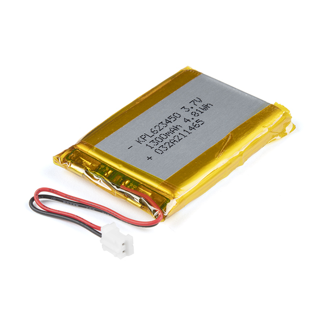
Of course, you will also need a single cell LiPo battery. Below are a few LiPo batteries to choose from in the SparkFun catalog.
Tools
Building a circuit using this breakout requires some assembly and soldering. You may already have a few of these items but if not, the tools and hardware below help with that assembly.
Prototyping Accessories
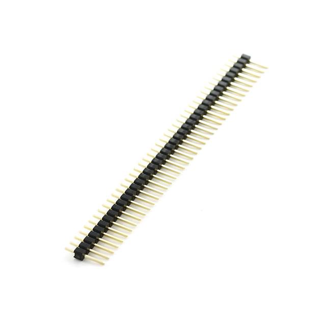
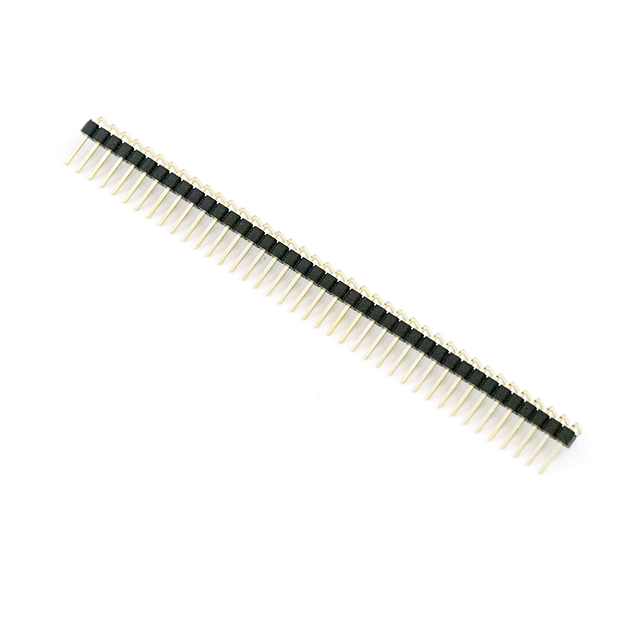
Depending on your setup, you may want to use IC hooks for a temporary connection. However, you will want to solder header pins to connect devices to the plated through holes for a secure connection. Depending on your application, you could use straight headers or right-angle headers. Of course, you could also solder wire as well.
For those that want to take advantage of the Qwiic enabled devices, you'll want to grab a Qwiic cable. Users can cut, strip, and solder half of a cable to easily connect the LiPo Fuel Gauge to a Qwiic-enabled microcontroller. For those that soldered male header pins to the board when prototyping, users can use a Qwiic cable with male pins or female sockets to connect without desoldering the header pins on the board. Note that this causes the board to have a higher height profile than soldering wires straight to the board.
Recommended Reading
If you aren’t familiar with the following concepts, we also recommend checking out a few of these tutorials before continuing.
Breakout Board (MAX17043) Hardware Overview
Revision Change: The LiPo Fuel Gauge - MAX17043 illustrated in this section highlights V1.2. The hardware is slightly different. In V1.2, the battery voltage is separate from VCC's pull-up resistors. When using V1.2, make sure to connect a regulated 3.3V from your microcontroller to provide voltage to the pull-up resistors.
In this section, we will highlight parts of the LiPo Fuel Gauge (MAX17043) breakout board. For users that have a built-in fuel gauge (MAX17043/MAX17048) already on your Arduino microcontroller, you can skip this section. The row of 1x3 header pins is arranged in a way so that you can insert the board a standard breadboard.
Top View
Bottom View
Battery and Power Input
The board includes a 2-pin JST connector to mate with single cell LiPo batteries. We have also broken out the pins to PTHs labeled as + and −. These can be used to solder the LiPo battery wires directly to the board and to your system's VBATT pin. The input voltage range is between 2.5V to 4.5V. Note that the nominal voltage of a single cell LiPo Battery is around 3.7V. Fully charged, the voltage is at around 4.2V. This input also powers the IC and should be connected to your system's power input as well.
Battery Input
Highlighted - Top View
Battery Input
Highlighted - Bottom View
Pull-Up Resistor's Voltage Input
VCC pin is connected to the I2C and alert pull-up resistors. This voltage input pin is different from the battery input pin. The maximum voltage that can be connected to this pin is 5.5V. This is typically 3.3V. If you decide to daisy chain the LiPo Fuel Gauge to Qwiic-enabled devices, we recommend using 3.3V.
Power Input
Highlighted - Top View
Power Input
Highlighted - Bottom View
I2C Pins
The I2C pins are broken out to PTHs. The 7-bit, unshifted address of the MAX17043 is 0x36. The address becomes 0x6C for write and 0x6D for read. There are two 2.2kΩ pull-up resistors connected to the SDA and SCL lines. These lines are connected to the VCC pin.
I2C Pins
Highlighted - Top View
I2C Pins
Highlighted - Bottom View
The ALT pin is the alert pin. The datasheet labels this as but we decided to label it as ALT due to the size of the board. This pin is active low indicating that there is a low state of charge. This pin can be connected to a microcontroller's interrupt pin. This pin can be left unconnected, and the status can be viewed though I2C.
Alert Pin Highlighted - Top View
Alert Pin Highlighted - Bottom View
Note: For users interested in using the alert pin to trigger an interrupt, we recommend checking out the Processor Interrupts with Arduino tutorial for more information.
Quick-Start Input Pin (QST)
The QST pin is for quick-start input. The datasheet labels this pin as QSTRT but we decided to label it as QST due to the size of the board. This allows users to reset the device through hardware. By default, the pin is connected to ground through a built-in 2.2kΩ resistor as suggested by the datasheet. A rising edge on this pin will initiate a hardware reset. One possible application is connecting this pin to microcontrollers reset pin should users decide to initiate a hardware reset. A reset can also be initiated through software as well.
Quick-Start Input Pin Highlighted - Top View
Quick-Start Input Pin Highlighted - Bottom View
Jumpers
By default, this 3-pad jumper is closed and located on the bottom of the board. The 2.2kΩ pull-up resistors are attached to the primary I2C bus; if multiple devices are connected to the bus with the pull-up resistors enabled, the parallel equivalent resistance will create too strong of a pull-up for the bus to operate correctly. As a general rule of thumb, disable all but one pair of pull-up resistors if multiple devices are connected to the bus.
Jumpers Highlighted - Bottom View
Board Dimensions
The board is 0.40" x 0.95". To make the board as small as possible, there are no mounting holes included on the board.
Hardware Hookup
Warning: The LiPo Fuel Gauge - MAX17043 illustrated in the hardware hookup uses V1.2. The hardware is slightly different. In V1.2, the battery voltage is separate from VCC's pull-up resistors. This requires you to connect a voltage from your microcontroller. The previous version (V1.1) connected VCC to the LiPo battery input which can vary between 3.0V and 4.2V. As a result, the pull-up resistors were also connected to the LiPo battery. This is fine for 5V tolerant microcontrollers. However, users should be careful when connecting any 3.3V devices that are not tolerant at those levels when using the previous version.
Now that we're familiar with the LiPo Fuel Gauge Breakout, let's connect it to a microcontroller and monitor a single cell LiPo battery!
LiPo Fuel Gauge Breakout Connections
For a permanent connection, we recommend soldering wires (or headers) to the PTHs on the breakout. We chose to use a combination of header pins and wires when prototyping. Of course, you could also solder wires to the breakout board as well. For a temporary connection during prototyping, you can use IC hooks like these.
How to Solder: Through-Hole Soldering
SEPTEMBER 19, 2013
This tutorial covers everything you need to know about through-hole soldering.
FEBRUARY 8, 2013
How to strip, crimp, and work with wire.
We recommend soldering the header pins and wires on one side. After soldering two rows of 1x3 header pins and a two-wire cable, your setup should look like the following image below. We decided to solder the straight header pins and wire all on the top side of the board. Depending on your application, you could solder the straight header pins on the bottom side as well. This will allow you to easily view the silkscreen if you decide to solder on the bottom. Make sure to wire the red wire to the PTH labeled as "+" and the black wire to the PTH labeled as "−".
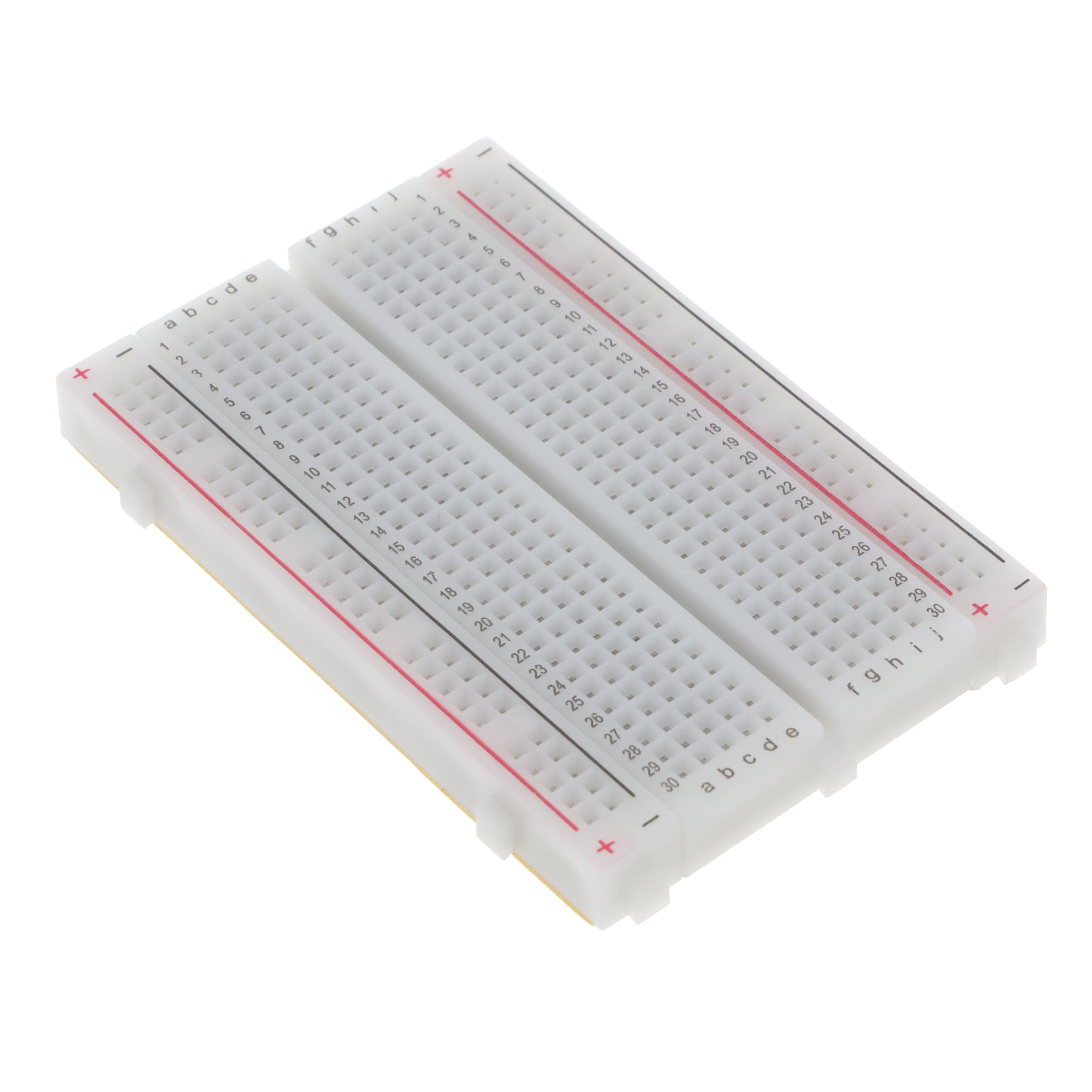
For users that want to prototype on a breadboard, you could insert the breakout board in the middle of a breadboard. Thanks to the header pin's plastic spacers, the cable can fit between the PCB and the breadboard. The image below shows the breakout board inserted into a mini breadboard. The edge of the board is on the edge of the mini breadboard so that you can disconnect/connect a LiPo battery to the 2-pin JST connector.
Connecting the LiPo Fuel Gauge to a Microcontroller
Connect the I2C pins, GND, and Vcc from LiPo Fuel Gauge to your microcontroller. We recommend using 3.3V for Vcc. Insert the battery into the LiPo Fuel Gauge's 2-pin JST connector. Then connect the JST cable that was soldered to your microcontroller's voltage input. In this case, we connected Qwiic cable to the RedBoard Artemis Nano's Qwiic connector and the 2-wire JST cable to the 2-pin JST connector.
Connecting a LiPo Charge Circuit
Users can include a LiPo charge circuit to safely charge the LiPo battery without needing to remove the LiPo battery from the LiPo Fuel Gauge. Below is one example that uses the LiPo Charger Plus to charge a single cell LiPo battery while it is also connected to an Arduino Pro Mini 3.3V/8MHz.
As the note indicates in the image, make sure to choose one power source for your Arduino microcontroller to avoid conflicting voltages: either from the LiPo battery or a USB-to-serial converter.
The Fritzing diagram shows male header pins connected to all but the VCC pin on the serial header. When connecting the USB-to-serial converter, this allows users to upload code or view serial data through the Arduino Serial Monitor without needing to worry about conflicting voltages from the FTDI's 3.3V pin.
Note: Certain microcontrollers have built-in charge circuits already integrated in the design so you may not need to add a charge circuit. Make sure to check your microcontroller for more information.
Connecting a Boost Circuit
Users can also include a boost circuit when users need a steady 5V input. Below is one example that uses the LiPo Charger/Booster 5V/1A to boost the voltage to 5V for the RedBoard Qwiic. Most microcontrollers usually run at 3.3V so you may not need to worry about boosting it for your Arduino. However, 5V could be used for addressable LEDs, servos, and motors.
As the note indicates in the image, make sure to choose one power source for your Arduino microcontroller to avoid conflicting voltages: either from the LiPo battery and charger/booster, or USB on the Arduino.
The Fritzing diagram does not show the wires disconnected from the LiPo charger/booster. However, this would be the better option to ensure that the battery is not connected to the RedBoard Qwiic input power pins. Users could also disconnect the 5V pin from the RedBoard Qwiic input power pin.
The other option would be to hack the USB cable and disconnect the 5V wire, which would be more of a hassle.
Connecting a Display
For users that are interested in viewing how much charge a single cell LiPo battery has available without a computer, users can attach a display to your microcontroller. Below is one example that adds a Qwiic Micro OLED to the first setup. Since you can control the display through I2C, it can be daisy chained using the Qwiic connectors. If you decide to use a different display, you will need to write code to output the values on the display.
Software Installation
Note: This example assumes you are using the latest version of the Arduino IDE on your desktop. If this is your first-time using Arduino IDE, library, or board add-on, please review the following tutorials.
If you've never connected an CH340 device to your computer before, you may need to install drivers for the USB-to-serial converter. Check out our section on "How to Install CH340 Drivers" for help with the installation.
SparkFun MAX1704x Fuel Gauge Arduino Library
The SparkFun MAX1704x Fuel Gauge Arduino Library can be downloaded with the Arduino library manager by searching 'SparkFun MAX1704x Fuel Gauge' or you can grab the zip here from the GitHub repository to manually install.
SparkFun Qwiic OLED Arduino Library
For users using a Qwiic Micro OLED to display the readings, the SparkFun Qwiic OLED Arduino Library can be downloaded with the Arduino library manager by searching 'SparkFun Qwiic OLED' or you can grab the zip here from the GitHub repository to manually install.
SPARKFUN QWIIC OLED ARDUINO LIBRARY (ZIP)
Note: There are two different Arduino libraries that can be used for the Qwiic Micro OLED. In this tutorial we are going to use the latest Qwiic OLED Arduino Library. You can use the older Micro OLED Breakout Arduino Library as well. However, you will need to adjust the example code to work with the alternative library.
Example 1: Simple Serial
In this example, we will be checking a single cell LiPo battery's voltage and the state of charge using the MAX17043. The output will be sent to the Serial Monitor.
Hardware Hookup
For this example, we will use the following parts from the Wishlist.
Solder and connect the circuit based on the following diagram as shown earlier. Instead of inserting the LiPo Fuel Gauge in a mini breadboard, you could connect the flexible Qwiic cable with female jumpers to the male break away headers that were soldered on the breakout board. For a more permanent connection, you could also cut the female jumpers, strip the Qwiic cable wires, and solder directly to the breakout board.
circuit_24
Upload Code
From the menu, select the following: File > Examples > SparkFun_MAX1704x_Fuel_Gauge_Arduino_Library > Example1_Simple. If you have not already, select your Board (in this case the RedBoard Artemis Nano), and associated COM port (in this case, COM27). Then hit the upload button.
code_25
Note: This example can also be used with other LiPo Fuel Gauges such as the MAX17044, MAX17048, and MAX17049. Simply comment out the line making an instance of the LiPo Fuel Gauge (i.e., SFE_MAX1704X lipo; by adding a single line comment (i.e., //. Then remove the single line comment line comment on the respective LiPo Fuel Gauge that you are using.
Open the Arduino Serial Monitor and set it to 115200 baud to view the serial output. You should see the voltage, battery percent, and alert flag. In this case, the single cell LiPo battery that was connected to the IC was almost fully charged and at about 4.20V. Since the battery was higher than the threshold that was set, the alert flag was not triggered and remained low.
com_26
Depending on how your battery is connected to your system, the reading can be a bit misleading. When there is a dedicated LiPo battery charging circuit actively charging the single cell LiPo battery and the MAX1704X initially reads the battery, the values can be higher. Try disconnecting the LiPo battery from the microcontroller's VBATT pin and hitting the reset button on your microcontroller to restart the code. The image below shows both wires disconnected from the RedBoard Artemis Nano's JST connector since we would be using a 2-pin JST jumper wire.
jst_27
Note: For boards that have a built in LiPo charger and Fuel Gauge, try closing out the Arduino Serial Monitor, disconnecting the USB, and disconnecting the LiPo battery. Then reinsert the LiPo battery, connect the USB cable, and reopen the Arduino Serial Monitor. The IC will recalculate everything. While the voltage will be misleading as the LiPo battery is being actively charged by the charge circuit, the remaining charge will be closer to what is expected.
By reopening the Arduino Serial Monitor, you may see a different reading reflecting the current state of the single cell LiPo battery rather than the output voltage of the charge IC. The image below shows actual voltage and remaining charge. You may want to add a display and write additional code as an alternative to connecting to a computer's serial terminal.
com_28
Example 4: MAX17048 KitchenSink
In this example, we will be checking a single cell LiPo battery's voltage and the state of charge using the MAX17048. The output will be sent to the Serial Monitor.
Hardware Hookup
For this example, we will use the following parts from the Wishlist.• 1x Reversible USB A to C Cable - 0.8m• 1x SparkFun IoT RedBoard - ESP32 Development Board• 1x LiPo Battery
In this case, we did not need to solder anything! The IoT RedBoard - ESP32 has a built in LiPo Fuel Gauge (MAX17048). By simply connecting a LiPo battery to the 2-pin JST connector and uploading code, we should be good to go! hookup_29
Upload Code
From the menu, select the following: File > Examples > SparkFun_MAX1704x_Fuel_Gauge_Arduino_Library > Example4_MAX17048_KitchenSink. If you have not already, select your Board (in this case the SparkFun ESP32 IoT RedBoard), and associated COM port (in this case COM27). Then hit the upload button. monitor_30
Open the Arduino Serial Monitor and set it to 115200 baud to view the serial output. You should see the voltage, battery percent, alert flag, and several more readings. In this case, the single cell LiPo battery that was connected to the IC was fully charged and at about 4.10V.
output_31
But wait! Remember the previous example? If you looked closely at the circuit of the SparkFun IoT RedBoard - ESP32 Development Board, there is also... you guessed it: a charge circuit built in. Try closing out the Arduino Serial Monitor, disconnecting the USB, and disconnecting the LiPo battery. Then reinsert the LiPo battery, connect the USB cable, and reopen the Arduino Serial Monitor. The IC will recalculate everything. In the image below, the voltage is a bit misleading since the charge IC is charging the LiPo battery and may not be the true representation of the LiPo battery's voltage. The remaining charge was closer to what was expected.
output_32
Note: For development boards that have a built-in charge circuit and fuel gauge, you may want to consider using a display to view the LiPo battery's true voltage and remaining charge. Otherwise, you could use a multimeter to measure the LiPo battery's voltage when a USB cable is not plugged in. Below is an example that uses the Qwiic Micro OLED to display the LiPo battery's voltage and remaining charge since the IoT RedBoard ESP32 includes a built-in charge circuit and fuel gauge (MAX17048). Just make sure to adjust the code for your fuel gauge and display. You can find some example code in the Combined Example A and Combined Example B later in this tutorial.
combined_33
More Examples!!!
Looking for more examples? Try checking the other examples in the Arduino Library. Example 2 is basically the same as Example 1, however the code was written for Arduino microcontrollers that have a different non-standard Wire and Serial ports. Example 3 is also based on Example but are for users that are using the MAX17044 IC (MAX17044 is configured for a dual-cell 2S pack). You will see the same readings on the Arduino Serial Monitor for both examples.
SPARKFUN MAX1704X FUEL GAUGE ARDUINO LIBRARY > EXAMPLES
Combined Example A: Simple Serial and Qwiic Micro OLED
In this example, we will be checking a single cell LiPo battery's voltage and the state of charge using the MAX17043. The output will be sent to the Serial Monitor and the Qwiic Micro OLED.
Hardware Hookup
For this example, we will use the following parts from the Wishlist.
• 1x Reversible USB A to C Cable - 0.8m• 1x SparkFun RedBoard Artemis Nano• 1x Break Away Headers - Straight• 1x SparkFun LiPo Fuel Gauge - MAX17043• 1x Flexible Qwiic Cable - Female Jumper (4-pin)• 1x SparkFun Micro OLED Breakout (Qwiic)• 1x Flexible Qwiic Cable - 50mm• 1x LiPo Battery• 1x JST Jumper 2 Wire Assembly
Solder and connect the circuit based on the following diagram as shown earlier. Instead of inserting the LiPo Fuel Gauge in a mini breadboard, you could connect the flexible Qwiic cable with female jumpers to the male break away headers that were soldered on the breakout board. For a more permanent connection, you could also cut the female jumpers, strip the Qwiic cable wires, and solder directly to the breakout board. Insert the Qwiic Micro OLED between the LiPo Fuel Gauge and the RedBoard Artemis Nano.
insert_34
After soldering and connecting the boards together, your setup should look similar to the following.
after_35
Depending on the microcontroller that you have and setup, you may want to disconnect the LiPo battery when uploading code and monitoring the LiPo battery through the Arduino Serial Monitor. The values may be misleading due the built in charge circuit that is on the RedBoard Artemis Nano. setup_36
Upload Code
Copy and paste following code into your Arduino IDE. If you have not already, select your Board (in this case the RedBoard Artemis Nano), and associated COM port (in this case, COM27). Then hit the upload button.
COPY CODE/
Disconnect the USB cable from your RedBoard Artemis Nano. Hit the reset button. disconnect_37
Looking close at the display, you should see the voltage, remaining charge, the alert flag indicating if the battery is low, and a battery meter icon. These values may be different depending on how much charge the LiPo battery has available.
looking_38
Note: For development boards that have a built-in charge circuit and fuel gauge, you may want to consider using a display to view the LiPo battery's true voltage and remaining charge. Otherwise, you could use a multimeter to measure the LiPo battery's voltage when a USB cable is not plugged in. Below is an example that uses the Qwiic Micro OLED to display the LiPo battery's voltage and remaining charge since the IoT RedBoard ESP32 includes charge circuit and fuel gauge (MAX17048). Just make sure to adjust the code for your fuel gauge and display.
adjust_39
Combined Example B: Simple Serial, Qwiic Micro OLED, Battery Icon
This example is pretty much the same as the previous combined example. However, we will add an additional battery meter icon.
Hardware Hookup
For this example, we will use the same parts as the previous combined example's Wishlist.
• 1x Reversible USB A to C Cable - 0.8m• 1x SparkFun RedBoard Artemis Nano• 1x Break Away Headers - Straight• 1x SparkFun LiPo Fuel Gauge - MAX17043• 1x Flexible Qwiic Cable - Female Jumper (4-pin)• 1x SparkFun Micro OLED Breakout (Qwiic)• 1x Flexible Qwiic Cable - 50mm• 1x LiPo Battery• 1x JST Jumper 2 Wire Assembly
hardware_40
Upload Code
Copy and paste following code into your Arduino IDE.
COPY CODE
To keep track of the icons that we create, we are going to create a header file with the *.ino. This is useful when writing code for big projects that involve a lot of components (e.g., RTK Express, RTK Express Plus, RTK Facet, RTK Facet L-Band, etc.). Click on the icon to create a new tab. We will name this icons.h.
file_41
Copy and paste the following code into tab.
COPY CODE
If you have not already, select your Board (in this case the RedBoard Artemis Nano), and associated COM port (in this case, COM27). Then hit the upload button. Disconnect the USB cable from your RedBoard Artemis Nano. Hit the reset button.
port_42
Looking close at the display, you should see the voltage, remaining charge, the alert flag indicating if the battery is low, and a battery meter icon. These values may be different depending on how much charge the LiPo battery has available!
display_43
Note: Similar to the previous example, you could use this code for boards that have a built-in charge circuit and fuel gauge. Just make sure to adjust the code for your fuel gauge and display. adjust_44
Troubleshooting
Not working as expected and need help? If you need technical assistance and more information on a product that is not working as you expected, we recommend heading on over to the SparkFun Technical Assistance page for some initial troubleshooting.
SPARKFUN TECHNICAL ASSISTANCE PAGE If you don't find what you need there, the SparkFun Forums are a great place to find and ask for help. If this is your first visit, you'll need to create a Forum Account to search product forums and post questions.
SPARKFUN FORUMS
Resources and Going Further
Now that you've successfully got your LiPo Fuel Gauge (MAX17043) up and running, it's time to incorporate it into your own project! For more information, check out the resources below:
• v1.2o Schematic (PDF)o Eagle Files (ZIP)o Board Dimensions (PNG)• Fritzing Parto v1.2o v1.1• Datasheet (PDF)o MAX17043 - Populated on LiPo Fuel Gauge Breakout Board, Wireless Joystick (SAMD21)o MAX17048 - Populated on QDuino Mini (ATMega32U4), SparkFun Thing Plus - ESP32 WROOM (USB-C), IoT RedBoard - ESP32• C Example Code (ZIP)• Particle Photon Library• Arduino Project Example• SparkFun Arduino Library• Arduino Library - Arduino library from user "porrey." This is another Arduino library that is available.• GitHub Hardware Repo