The PM6641 demonstration board is a monolithic voltage regulator (VR) module with internal power MOSFETs, specifically designed to supply DDR2/3 memory and chipset in ultramobile PC and real estate constrained portable systems.
A very low noise differential power supply for split rail systems requiring low noise +5V and -5V (higher or lower voltage is possible). This design is fully isolated and capable of floating to over 500V differential from Vin to Vout (higher is possible).
The XRP7714EVB-DEMO-1, XRP7714EVB-DEMO-2, and the XRP7714EVB-DEMO-2P demo boards are complete, working, four channel, power systems measuring either 2”x2”, or 2”x2.5” capable of delivering over 35 watts. They provide 3.3V, 2.5V, 1.8V, and 1V at a maximum of 4 amps per channel. The 2.5V, 1.8V, and 1V supplies can be adjusted in 50mV increments, and the 3.3V supply is adjustable in 100mV increments.…
The LMR24220 Multi-Rail reference board implements an extremely compact solution. It is designed to convert from 12V or 24V rails down to typical point-of-load voltages of 3.3V, 1.8V and 1.2V. This design utilizes an LMR24220 Nano Regulator and two LMZ10501 Nano Modules to demonstrate a complete solution for space constrained multi-rail applications.
Demonstration circuit 1453A features the LTM®4619EV, the high input voltage, high effi ciency, high density, dual 4A step-down power module. Derating is necessary for certain VIN, VOUT, and thermal conditions.
The two outputs are interleaved with 180° phase to minimize the input ripple
This user guide describes the hardware and software for the evaluation of the ADP5051/ADP5053, including detailed schematics and printed circuit board (PCB) layouts.
Demonstration Circuit 1582B featuring the LTC3108 is a highly integrated DC/DC converter optimized for harvesting and managing energy from extremely low input voltage sources such as thermoelectric generators (TEG). The step-up topology operates from input voltages as low as 20mV.
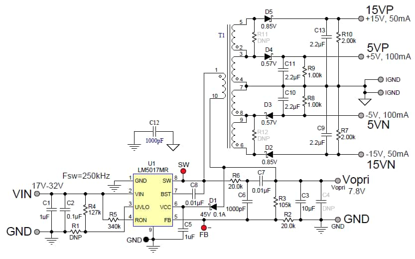
This Flybuck reference design uses the LM5017 buck regulator to generate four isolated outputs: ±15V@50mA and ±5V@100mA. The regulation is done on the primary side, and thus no opto-coupler is needed. The overall load/line regulation for each output is within +/-5%. The input voltage range is from 17V to 32V. It's suitable for applications requiring multiple positive and negative bias voltage rai…
This user guide describes the hardware and software for the evaluation of the ADP5050/ADP5052 and includes detailed schematics and printed circuit board (PCB) layouts.
Demonstration circuit 2066A is a dual-output, high efficiency, high density, μModule regulator with 4.5V to 16V input range. Each output can supply 18A maximum load current. The demo board has a LTM®4677 μModule regulator, which is a dual 18A or single 36A step-down regulator with digital power system management. Please see the LTM4677 data sheet for more detailed information.
 Settings
 Fast Delivery
 Payment Types


 Marketplace Product